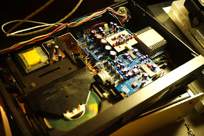
Dissecting my Sony A7RII :Teardown

I got a Sony A7RII dust cheap due to the fact that it submersed in a sand dune and was blew by compressed air. Please listen. Don't blow the sand off from your camera or lens by compressed air. The air will drive the sand going deeper into your camera. Just shake or brush the sand off the camera.
So I need to clean the whole camera and/or replace the shutter if sand was getting into it. The A7Rii indeed in good condition only with stuck shutter occasionally.
Before dissembling the camera you need some tools.
1. JIS srew driver (not the normal Philips screw. Using Philips screw drive will slap the screws, period). Stop if you don't have.
2. Alcohol. I use 90% ethanol and it can dissolve the black tape or the screw paint.
3. Scotch tape. To protect the heat pad
4. Small plastic bag or container to store the parts
5. Conductive bag. To store the main circuit board and imager/stabilizer assembly.
Here is the procedure to dissemble the whole camera.
Basic sequence to dissemble the camera to reach the shutter module (or even the lens connector)
1. Removing the bottom plate/tripod plate/battery compartment cover (3 mins)
2. Removing the LCD (10 mins)
3. Removing the back cover/EVF casing(5 mins)
4. Removing the wheel control connector (4 mins)
5. Removing the steel (outer) cage (3 mins)
6. Removing the Card Slot (2 mins)
7. Removing the Shielding/heatsink cage (5mins)
8. Removing the EVF (2 mins)
9. Removing the handgrip (8 mins)
10. Removing the circuit board (20 mins)
11. Removing the top (5 mins)
12. Removing the mic/phone cover (1 mins)
13 Removing the steel (inner) cage (8 mins)
14. Removing the imager/stabilizer module (3 mins)
15. Removing the min/phone module (2 mins)
16. Removing the shutter module (4 mins)
17. Separate the front plate and main frame (4 mins)
Total 90 mins
Screw type used in camera
M1 3.5 JIS
M1 2.5 JIS
M1 2.5 Self tapping
M1.5 JIS
+ some M2 screws
Detailed Procedures
1. Remove the bottom plate - Total 7x M1 3.5 screws a

2. To remove the LCD

- release the ribbon cable cover by slide it out
- release the cable connector cover by slide it upward
- release the cable connector lock
- pull the cable out of the connector
- use alcohol to dissolve the glue between the cable and the LCD frame
- remove 4 x M1 2.5 screws from the frame support
- remove two M1 3.5 crews on the back
- remove the M1 3.5 screw near to REC button
- remove two M1 3.5 screws on the bottom near to the handgrip
- remove one M1 3.5 on the left
- remove the M1 3.5 screw inside the cover of the mic/phone
- Totally 7 M1 3.5 screws
- remove four M1 3.5 screw from viewfinder casing
- remove the one M0.5 selftapping screw on diopter

- slide the wheel control out of the slot and disconnect the cable
- also disconnect the wifi cable
- Loose the cable connected to the top carefully, with the REC button.
- remove three M1 3.5 (two self tapping screws on the right and one M1 3.5 on the left)
- ** better to mark the screw hole on the cage
- remove the M1 2.5 screw onleft
- release the cable by unlock the connector
- ** the leg on the bottom cage is placed between the cage and metal plate
- loose the LCD cable by release the connector lock
- remove 3 x M1 2.5 JIS
- dissolve the glue on tape and remove it


- due to the stickiness of the heat pad behind the EVF, pull the EVF carefully. If not, he LCD will be separated from the optics.
- release the cable connectors
- release all the cables connected to the board.
- there are two main type of flat cable connectors, one with lock and the other without.

10. Removing the Handgrip
 |
| This is the M1 3.5 screw securing the top |

- remove two screws inside the grip. (the top one is M1 self tapping and the lower one is M1 3.5)

- remove the cable (front) carefully. No lock, just slide it out


- remove the screws (2x M1.5) behind the EVF
- remove the screws (2x M1 3.5 ) on both side
- release the cable on the right side (cable lying along the battery compartment))
- remove the top slowly since one of the connector are on the battery compartment

13. Removing the steel inner cage
- Four screws (M1 2.50
- mark the hole
- The memory backup battery is on the back side
- Three M1.5 screws hold the module.
- Be-careful the shims are under the module and make sure you mark them down.

- peel the foam off carefully and unscrew one M1 3.5 screw (inside the hole which covered by the foam)
- unscrew 3x M2 5 screws.

- remove the lens mount (4x screw M2 3.5)
- remove the ring spring
- remove two screws near to the EVF (M1.5)
- remove two screw near the bottom (M1.5)
- ** the lens release consists of three pieces, the pin, the spring and the plastic guide


Once the A7RII is in pieces. Time to clean up all the parts. Compressed air and vacuum cleaner are used to remove the debris and dust, in this case, sand.
The shutter and charging unit were contaminated by the sand and I decided to change the shutter but keep the shutter charge unit. The whole charge unit was dissembled and clean and lubricated by dry silicon grease.
The updated shutter unit for A7RII is COPAL AFE3379. I still cannot find a way to reset the shutter count though.
I will post the video showing how to put the parts back to a working camera.
Tag: dismantle A7RII
Comments
hope this help
There is really a strange thing about the A7R2 Copal... A common problem is that the shutter unit has a strong infrared leak, which is a big problem for astrophotography. Have you ever noticed this problem?
Actually, I don't know if the 3379 or th 3360 is installed on my device, but I have a strong infrared leak. The A7III have no leak and they use the Copal 3360. To control if you have this problem just take a picture with the device closed, 30" ISO 25600, you should see a purple glow.
Do you know why th afe 3379 is now the "new" Copal for A7R2?